


|
Reference Standards
|
EN 61558-1,2-20
|
|
Frequency
|
50/60Hz +/-5%
|
|
Thermal Index
|
T155 / F
|
|
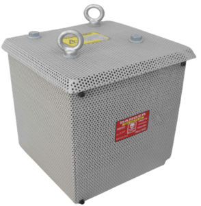
Ingress Protection
|
IP20 to IP32
|
|
Efficiency
|
> 85% or Custom Designed
|
|
Primary Voltage
|
0/220/440V or Custom Designed*
|
|
Secondary Voltage
|
0/115/230V or Custom Designed*
|
|
Terminal Blocks
|
Touch Proof Screwless
|
|
Varnish
|
Vacuum Pressure Impregnation Processed
|
|
Leads Termination
|
Top, Side, Front or Custom Designed*
|
|
Mount Type
|
Foot, DIN Rail or Custom Designed*
|
|
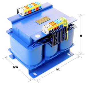
Product Cat #
|
Capacity kVA
|
ML (mm)
|
MW (mm)
|
OL (mm)
|
OW (mm)
|
H (mm)
|
Weight Kgs
|
|
|---|---|---|---|---|---|---|---|---|
|
135-0.02k-3-00X-XX
|
0.02
|
On request
|
160
|
130
|
160
|
5.0
|
||
|
135-0.05k-3-00X-XX
|
0.05
|
On request
|
160
|
150
|
160
|
5.5
|
||
|
135-0.15k-3-00X-XX
|
0.15
|
On request
|
160
|
175
|
160
|
80.0
|
||
|
135-0.3k-3-00X-XX
|
0.30
|
On request
|
200
|
175
|
175
|
11.0
|
||
|
135-0.5k-3-00X-XX
|
0.50
|
On request
|
200
|
200
|
175
|
12.0
|
||
|
135-0.75k-3-00X-XX
|
0.75
|
On request
|
230
|
150
|
250
|
14.5
|
||
|
135-1k-3-00X-XX
|
1.00
|
On request
|
230
|
150
|
250
|
16.0
|
||
|
135-1.25k-3-00X-XX
|
1.25
|
On request
|
230
|
175
|
250
|
20.0
|
||
|
135-1.5k-3-00X-XX
|
1.50
|
On request
|
230
|
175
|
250
|
21.0
|
||
|
135-2k-3-00X-XX
|
2.00
|
On request
|
250
|
250
|
250
|
28.0
|
||
|
135-2.5k-3-00X-XX
|
2.50
|
On request
|
300
|
200
|
300
|
37.0
|
||
|
135-3k-3-00X-XX
|
3.00
|
On request
|
300
|
250
|
350
|
40.0
|
||
|
135-3.5k-3-00X-XX
|
3.50
|
On request
|
300
|
250
|
400
|
47.0
|
||
|
135-4k-3-00X-XX
|
4.00
|
On request
|
330
|
250
|
350
|
53.0
|
||
|
135-4.5k-3-00X-XX
|
4.50
|
On request
|
350
|
300
|
350
|
60.0
|
||
|
135-5k-3-00X-XX
|
5.00
|
On request
|
350
|
300
|
350
|
70.0
|
||
Intermittent / Load specific duty cycle rated transformers can be manufactured on request
Transformer capacities other than the above can be manufactured with no MOQ constraints
Note :
1. All the dimensions are in mm
2. X, XX, * is for product codification based on standard/ custom designed specification
3. IGES file format / dimensional drawing can be sent on request
4. The above Transformer is only for illustration and may vary for optimum structural integrity, and specification.
| Cookie | Duration | Description |
|---|---|---|
| cookielawinfo-checkbox-analytics | 11 months | This cookie is set by GDPR Cookie Consent plugin. The cookie is used to store the user consent for the cookies in the category "Analytics". |
| cookielawinfo-checkbox-functional | 11 months | The cookie is set by GDPR cookie consent to record the user consent for the cookies in the category "Functional". |
| cookielawinfo-checkbox-necessary | 11 months | This cookie is set by GDPR Cookie Consent plugin. The cookies is used to store the user consent for the cookies in the category "Necessary". |
| cookielawinfo-checkbox-others | 11 months | This cookie is set by GDPR Cookie Consent plugin. The cookie is used to store the user consent for the cookies in the category "Other. |
| cookielawinfo-checkbox-performance | 11 months | This cookie is set by GDPR Cookie Consent plugin. The cookie is used to store the user consent for the cookies in the category "Performance". |
| viewed_cookie_policy | 11 months | The cookie is set by the GDPR Cookie Consent plugin and is used to store whether or not user has consented to the use of cookies. It does not store any personal data. |