Three Phase Isolation Control Transformers
- Home
- Three Phase Isolation Control Transformers
Brochures
Isolation Transformers
Control Transformers
Industrial Transformers
Reactors / Chokes
Other Transformers
Filters
Three Phase Isolation Control Transformers
|
Reference Standards
|
EN 61558-1,2-20
|
|
Frequency
|
50/60Hz +/-5%
|
|
Thermal Index
|
T155 / F
|
|
Ingress Protection
|
IP20 to IP32
|
|
Efficiency
|
> 85% or Custom Designed
|
|
Primary Voltage
|
0/220/440V or Custom Designed*
|
|
Secondary Voltage
|
0/115/230V or Custom Designed*
|
|
Terminal Blocks
|
Touch Proof Screwless
|
|
Varnish
|
Vacuum Pressure Impregnation Processed
|
|
Leads Termination
|
Top, Side, Front or Custom Designed*
|
|
Mount Type
|
Foot, DIN Rail or Custom Designed*
|
|
Product Cat #
|
Capacity kVA
|
ML (mm)
|
MW (mm)
|
OL (mm)
|
OW (mm)
|
H (mm)
|
Weight Kgs
|
|
|---|---|---|---|---|---|---|---|---|
|
135-0.02k-3-00X-XX
|
0.02
|
On request
|
160
|
130
|
160
|
5.0
|
||
|
135-0.05k-3-00X-XX
|
0.05
|
On request
|
160
|
150
|
160
|
5.5
|
||
|
135-0.15k-3-00X-XX
|
0.15
|
On request
|
160
|
175
|
160
|
80.0
|
||
|
135-0.3k-3-00X-XX
|
0.30
|
On request
|
200
|
175
|
175
|
11.0
|
||
|
135-0.5k-3-00X-XX
|
0.50
|
On request
|
200
|
200
|
175
|
12.0
|
||
|
135-0.75k-3-00X-XX
|
0.75
|
On request
|
230
|
150
|
250
|
14.5
|
||
|
135-1k-3-00X-XX
|
1.00
|
On request
|
230
|
150
|
250
|
16.0
|
||
|
135-1.25k-3-00X-XX
|
1.25
|
On request
|
230
|
175
|
250
|
20.0
|
||
|
135-1.5k-3-00X-XX
|
1.50
|
On request
|
230
|
175
|
250
|
21.0
|
||
|
135-2k-3-00X-XX
|
2.00
|
On request
|
250
|
250
|
250
|
28.0
|
||
|
135-2.5k-3-00X-XX
|
2.50
|
On request
|
300
|
200
|
300
|
37.0
|
||
|
135-3k-3-00X-XX
|
3.00
|
On request
|
300
|
250
|
350
|
40.0
|
||
|
135-3.5k-3-00X-XX
|
3.50
|
On request
|
300
|
250
|
400
|
47.0
|
||
|
135-4k-3-00X-XX
|
4.00
|
On request
|
330
|
250
|
350
|
53.0
|
||
|
135-4.5k-3-00X-XX
|
4.50
|
On request
|
350
|
300
|
350
|
60.0
|
||
|
135-5k-3-00X-XX
|
5.00
|
On request
|
350
|
300
|
350
|
70.0
|
||
Intermittent / Load specific duty cycle rated transformers can be manufactured on request
Transformer capacities other than the above can be manufactured with no MOQ constraints
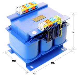
- ML – Mounting Length
- MW – Mounting Width
- OL – Outer Length
- OW – Outer Width
- H – Height.
- Refer to the above product image to correlate the measurement location
Note :
1. All the dimensions are in mm
2. X, XX, * is for product codification based on standard/ custom designed specification
3. IGES file format / dimensional drawing can be sent on request
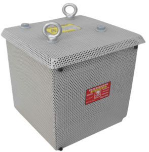
4. The above Transformer is only for illustration and may vary for optimum structural integrity, and specification.


